
Ford Mustang Oil Pressure Gauge Project:
I am leaving this page here because it has a lot of historical data in it, but since my web page editor has screwed it up so badly, I have put the final report on the oil pressure and temperature gauge upgrade in the Interior section of the site here.
For those of you who don't know it, the stock oil pressure gauge is really just an idiot light. The sender is a switch that closes and turns that gauge on when the oil pressure is above 6PSI and turns the gauge off when it is below 6PSI. This is a waste of valuable cockpit instrumentation space.
I plan to characterize the stock Mustang oil pressure gauge to see if it would be possible to develop a circuit that would allow us to change the sender to a real pressure transducer and make the stock oil pressure gauge work like a real oil pressure gauge.
It is possible that the gauge is too crappy to use, so no promises.
I am working off a 96 Mustang Helms manual and the 96 Mustang EVTM plus what
I have found on the forums. I have an 04 Mustang Helm manual and wiring manual,
but all I have found there is the oil pressure switch. There are no details for
the 04 gauge itself in those manuals, at least that I could find.
Somewhere in the neighborhood of 1989, Ford went from a pressure transducer
driving the gauge to a pressure switch driving the gauge. After that, I know
they put a plastic pin in the Fox body gauges to hold them at the high-normal
reading when the pressure switch is closed, rather than going all the way to the
top of the gauge.
The older Fox senders were variable resistor style pressure transducers. Based
on the circuit diagram, it looks like the transducer varied the current flowing
through an ammeter to show you the actual oil pressure. The resistance would
vary from 9.7 ohms at the High mark to 74 ohms at the Low mark. In the newer
ones, such as diagrammed in my 96 EVTM, there is only a switch to ground and an
internal 20 ohm resistor. Other than that, the gauge mechanism for the old
gauges look the same as the new gauges.
Old Fox Oil Pressure Gauge Schematics:
It also seems that the old variable resistor pressure transducers were
notoriously unreliable.
I suspect that all of the gauges from 1990 and up are basically the same and all
have the 20 ohm resistor and the pin.
96 Mustang Oil Pressure Gauge Schematics:
03 Mustang Oil Pressure Gauge Schematics:

I think we have a number of options here.
1. If we want full travel of the gauge, the plastic pin will need to be broken
off if ford still puts them in. The 20 ohm resistor may have made the pin
unnecessary. I need to look inside one to know for sure. We can run with limited
high end range if we don't want to take the cluster apart. I am more interested
in too low oil pressure than too high, so I am not sure yet. If anyone is
willing to live with limited upper range, this may not be needed.
2. It is possible, if we can find a pre 89 pressure transducer sender, that it
will replace the switch, and just work, although the calibration may be off due
to the 20 ohm internal resistor. I also need to look inside the cluster to see
if that 20 ohm resistor can be shorted out to eliminate it from the circuit.
3. If I can characterize the way the gauge works, It may be possible to make a
small circuit that will take the accurate voltage output from a modern
strain-gauge pressure transducer such as the ones Autometer uses, and translate
that into the upside down current signal that the gauge apparently needs to
operate. If this is the case, we might be able to make the stock gauge pretty
darned accurate.
Thanks to some of the guys on Corral, I have found a number of web sites that describe how other Ford owners have replaced their switches with the old Fox body senders and shorted out the 20 ohm resistor to get it to work as a real oil pressure gauge. Here are the part numbers they listed:
Motorcraft SW-1547-B
Motorcraft E4ZZ-9278-A
Standard Motor Products: PS-60
Echlin or Napa: OP6091
My local parts shop did a cross reference on the Motorcraft E4ZZ-9278-A part number and sold me a Borg Warner S334. ($21.00)
I installed a compressor quick-release fitting on the sender and connected it to my compressor and a digital ohm meter.

With 0 PSI, the resistance was infinite. The pressure gauge on my compressor is not calibrated below 10 PSI. As I pressurized the sender, before it hit 10PSI, the Ohm meter dropped to the thirties and then bounced all over the map as I pressurized the sensor to over 70PSI. I then turned off the compressor and released pressure till the gauge read 70PSI and read the resistance. I did the same at decreasing 5 degree increments. Here is the data:
PSI Ohms
70 17
65 18
60 20
55 23
50 21
45 24
40 27
35 27
30 26
25 26
20 31
15 40
10 32
Less then 10 PSI, the resistance went infinite again.

As you can see from the graph, the sensor does roughly increase resistance as pressure decreases. I overlayed a linear regression line to show the line it approximates. But it sure does not look very clean. Please note that my little compressor was unable to go over 70PSI, so I am not sure what the sensor upper range is.
I will show how you can use the old Fox sensor with the new modified gauge, but I think I want to design the circuit to use a modern sender to make it much more accurate.
1/27/09: Received an Autometer 2242 0-100 PSI analog sender today:

It cost me $30.00
First I characterized the Autometer 2242 sensor.
PSI Resistance in Ohms
75 70
70 73
65 79
60 85
55 95
50 105
45 113
40 120
35 130
30 140
25 148
20 156
15 170
10 190
0 267

As you can see from the graph, the Autometer 2242 is a much better pressure transducer than the stock Fox sender. I ran a linear trendline and the sensor is pretty darned close to the line. The equation for the trendline is yPSI=108.4-0.56xOhms. Assuming the linear sensor performance continues to 100 PSI (which I must do since I have such a wimpy compressor) then you will see 15 Ohms at 100 PSI.
We know from the documentation above that the Fox gauges read from 9.7 Ohms at the High mark to 74 ohms at the Low mark.
If we want to make the circuit simple, we can put a resistor in parallel with the sensor to lower the resistance of the sensor. Remember the equation for parallel resistors: 1/R=1/R1+1/R2. We can use this formula to set the resistance so that the gauge will reflect 10 PSI at the low mark, which I would be happy with. Then we can see where 100 PSI will land on the gauge.
At 10 PSI the sensor gives a resistance of 190 ohms. If we want to know the resistor we need to add across that to get the desired resistance of 74 Ohms, we use the equation: 1/74=1/190+1/R. If we solve for R, we get R=121 ohms.
If we run a 121 Ohm resistor in parallel with the sensor, what resistance will we see at 100 PSI? At 100 PSI, the sensor is expected to show about 15 ohms. To find out what the effective resistance of the sensor with the resistor at 100 PSI, we solve the equation 1/R=1/15+1/121. R=about 13.3 ohms. Since the High mark on the gauge is at 9.7 ohms, we know that at 100 PSI we will almost make it to the High mark on the gauge.
This implies that the circuit we need to make this work is a 121 Ohm resistor in parallel with the sensor.
Until I can get a gauge to play with, I will be unable to demonstrate the linearity of the gauge, or calibrate the pressures with the letters on the gauge. But it looks like the circuit we will need is a simple resistor. How cool is that?
2/1/09: Please keep in mind that everything I have done to this point is theoretical because I have not been able to find any real instrument clusters to play with to this point.
I took some pictures of my gauge so I can do a little playing around with how the gauge ranges may play out with old and new gauges and with different parallel resistance values. Here are pictures of the gauge with the switch open (0 PSI) and closed (>6 PSI):


We know that the gauge reads between M and A when the sender resistance is 20 Ohms. We know it reads below the Low mark when sender resistance is infinite. If the documentation above is correct, then we know that the gauge reads at the High mark at 74 Ohms and the Low mark at 9.7 Ohms. Based on these known points on the gauge, I tried to interpolate what sender resistance corresponds with which gauge needle positions. It looks like the gauge is not very linear, but remember, there are only guesses.
| Gauge Point | Sender Res |
| High | 10 |
| High-Normal | 13 |
| L | 16 |
| A | 18 |
| M-A | 20 |
| M | 25 |
| R | 35 |
| O | 45 |
| N | 55 |
| Low-Normal | 65 |
| Low | 75 |
| Zero Press. | 85 |
I also made a spreadsheet that allowed me to change the parallel resistor value to see what effect different resistors had on the range of the oil pressure gauge. I did this for both the old gauges with the 20 Ohm resistor shunted out and for the new gauges with the intrinsic 20 Ohms of resistance.
With a little Photoshop magic, I made a gauge face without the needle and then added needles at the various points.
Here is the guestimated resistance and oil pressure for each point on the gauge for the old gauge with a 100 Ohm resistor and the new gauge with a 60.4 Ohm resistor:

Sender resistance = 10 Ohms, Old gauge ~ 102 PSI, New Gauge =
Will not get there

Sender resistance ~ 13 Ohms, Old gauge ~ 100 PSI, New Gauge =
Will not get there

Sender resistance ~ 16 Ohms, Old gauge ~ 98 PSI, New Gauge =
Will not get there

Sender resistance ~ 18 Ohms, Old gauge ~ 96 PSI, New Gauge =
Will not get there

Sender resistance = 20 Ohms, Old gauge ~ 95 PSI, New Gauge ~
108 PSI

Sender resistance ~ 25 Ohms, Old gauge ~ 90 PSI, New Gauge ~
105 PSI

Sender resistance ~ 35 Ohms, Old gauge ~ 79 PSI, New Gauge ~
97 PSI

Sender resistance ~ 45 Ohms, Old gauge ~ 63 PSI, New Gauge ~
85 PSI

Sender resistance ~ 55 Ohms, Old gauge ~ 41 PSI, New Gauge ~
62 PSI

Sender resistance ~ 65 Ohms, Old gauge ~ 6 PSI, New Gauge ~
11 PSI

Sender resistance = 74 Ohms, Old gauge ~ 0 PSI, New Gauge ~ 0
PSI

Sender resistance >= 85 Ohms, Old gauge = 0 PSI, New Gauge ~
0 PSI (Probably won't get there)
Remember, these are only guesses until I get my hands on a real pair of gauges.
(Edit posted 2/23/10:)
I figured out that the Autometer 2242 with a 121 ohm resistor in parallel would work, but when I analysed how well it would work, it could not drive the needle over the entire scale.
Specifically, with the car's voltage at 12V, the resistor would drive the needle to the L mark at 0 PSI, up to 90 degrees, between the R and the M, at 100 PSI. And the needle position would vary some as Vbatt varied.
I tried using a different resistor in parallel with the sender, but that moved the zero point up above the L mark and did not give us any more range in needle movement. So it would not work, unless you are ok with using only half the scale of the gauge.
02/10/09: I have some bad news for 99+ Mustang owners. Ford is not making this hack easy. I got my hands on a loaner 03 Cobra instrument cluster. I was not allowed to run any experiments on it, but I was able to trace the circuits on the circuit board. The Helm manual implied that there was a direct connection from the oil pressure switch to the gauge, but this is not true. I was able to trace the oil pressure signal from the switch onto the cluster circuit board, and it went to the base of transistor Q11, the emitter or collector of transistor Q20, C22, a two lead surface mount device labeled "CSP" and through two resistors (R86 and R51) to pins 10 and 11 of IC1 respectively. IC1 is marked "7048OFB". I could not find any reference to such an IC on the internet.
Working backwards from the gauge connector to the circuit board, I found 4 pins on the gauge. One of the pins is grounded. The other three run to an integrated circuit labeled IC8. IC8 is marked "N710021CFMBFGA". I was able to find references to this device as a Philips Semiconductor device, in stock at several locations, but I could not find a datasheet.
I can see the confusion my forum posts were causing when I looked at the 03 gauge face. There is no word "NORMAL", just an icon of an oil can:

When I get the 03 cluster I can hack up next week, I will see how the meter works to see if I can take the gauge itself out of the circuit to add my own.
2/24/09:
I received the 03 Mach1 cluster with the GT face plate last week. I wired up some old Honda ECU connector pins up, covered them with shrink tubing and hooked them up to the power, ground and oil pressure sender pins on the cluster connector.
When I powered up the cluster, it came right up. The gauges each do a full sweep and then settle back to their zero point as they should. I calibrated the needles as best I could. I took some pictures of the setup in action, but I did not yet have the voltmeter calibrated:


As you can see above, the cluster draws about 640mA. When I ground the oil pressure pin, the oil pressure goes to high-normal.
When I held in the button and powered it up, it did its power-on sweep, then all of the odometer segments lit for a second, then it went to all dashes, then I got a code that looked like an upside-down F53F. Then it went back to dashes and normal operation.
Next steps are to characterize the gauge driver voltages during the power-up sweep, so I can verify that the gauge drivers I am looking at will work.
I dug into it tonight and verified that the gauges are air-core gauges. The
horizontal pins power the coil that provides the reference magnetic flux and the
vertical pins power the coil that provides the deflection magnetic flux. Each
coil has an impedance of 181 Ohms.
With the horizontal pins powered by 5.4V, the needle goes to the center of the
gauge. Current through the deflection coil (vertical pins) moves the meter to
one side, more current gives more deflection. If you reverse the direction of
the current, you reverse the needle movement to the other side of the gauge.
After I ran all my tests, I took the PCB off the cluster to access just the
gauges. I put 5.4V across the horizontal pins and found that I had the oil
pressure gauge and the voltage gauge where the needles were nearly exactly
centered. But I was way off with the temperature and fuel gauges, so I centered
them while I had it apart.
The fuel level and temperature data must come from the data link since there are
no independent inputs for them. So I ignored the temp and fuel gauges.
When you first power on the cluster, it sweeps the oil pressure gauge to the H
for a second, then it goes back to a little below the L for a second, and then
to the L if the oil pressure switch is open or to high-normal if the oil
pressure switch is closed to ground.
Here are the voltages I read on the oil pressure gauge vertical pins at those
points. For the voltage across the deflection coil, I put the negative DVM lead
on the bottom pin and the positive DVM lead on the top pin:
Needle Top
Bottom Across
Position Pin
Pin Pins
At the H 0.9V
4.9V -4.0V
Below L 8.9V
0.9V 8.0V
At L 7.6V
0.9V 6.7V
Hi-Normal 0.9V
1.2V -0.3V Oil Pressure pin
grounded
Since I had control of the voltage, I figured I would characterize the voltage gauge while I was at it. I learned that the voltage gauge shows the driver when the voltage is falling below 12V, but the needle does not move much at all above 12V. Here is the data that I took for the voltage gauge:
15V: reads a touch over mid-gauge 14V: reads a touch over mid-gauge 13V: reads a touch over mid-gauge 12V: reads a touch over mid-gauge 11V: reads at about 33% of the normal range 10V: reads at Low-Normal mark 9V: reads at the L mark 8V: reads a little below the L mark
So now you know what your voltage gauge reading means.
It looks like the air-core gauge drivers will work for us.
Now, we can play with how to isolate the gauge from the circuit.
2/25/09:
Dave Bower on ModFords had a good idea. Since the stock volt gauge and temp gauge are also retarded, with the addition of a temp sensor, I can make all three stock gauges real for the 99+ cars. Since the gauge driver circuit I selected has two minor gauge drivers on it, I can do at least two. But I think if I use one half of the major gauge driver in the driver chip, I can drive all three minor gauges with one driver chip. As a result, I am doing the testing work on the fuel gauge so if I break anything, I can still work on the other three.
I need to apologize for the fuzziness of some of these pictures. I am having trouble with the macro mode of my camera.
In order to isolate the gauges from the PCB, the white plastic cover shown above needs to be removed, exposing the PCB:

There is one gray connector at the bottom center of the cluster (I have the cluster upside-down in these pictures) that needs to be unplugged in order to pull the PCB off of the cluster:

The PCB will now just slide off of the gauge connectors and off the cluster at this point:

Here is a close-up of the gauge pins:

I found that standard Molex female pins will fit on the male gauge pins. If is a very tight fit, but that is what you want. This is a picture with a stock Molex pin on the gauge pin:

Here I tested the Molex pin to ensure it will fit through the PCB connectors:

At the very top of the Molex pin, there is a piece that is designed to be crimped on the insulation of the wire you are pitting on the pin. For clearance purposes, I needed to cut that away from the pin. Then I soldered a wire to the pin and crimped it. I covered that with a little shrink tubing. I needed to leave the wire exposed at the top of the pin because the shrink tubing would not bend enough for the white plastic cover to go back on. This is what the wires with the pins looks like:

Here I test fit the wires on the pins:

When I put the PCB over the Molex pins, the PCB stripped the shrink tubing from the pins, causing a short through to the PCB. I learned that the best way to isolate the pins from the PCB is to bend the connectors away from the hole. Then I used a 5/16" drill bit to open up the hole through the PCB just a tiny bit. The gauge connectors I modified, are the lower left ones in the picture below. You can see how I bent the connectors away from the hole in for the connector at the lower connector and the one above it. You can see how I opened up the hole a bit in the one at the bottom of the picture, compared to the one above it. The ones to the left and right were left stock for this picture:

After that, I bent the connectors and drilled open the holes for the rest of the connectors. If anyone would want to return the cluster to stock, all that would need to be done is to remove the Molex pins, bend the PCB connectors back so they will contact the gauge pins, and use the stock oil pressure switch.
Here is a picture of the PCB pushed back down on the cluster. The tops of the Molex pins where the wire is soldered to it are not round, they are oblong. You need to ensure the Molex pins are turned so the oblong part matches the oblong holes in the PCB before you can push the PCB down onto the cluster. I tested to ensure that the gauges are, in fact, isolated from the PCB and they are.

Now the gray connector at the bottom of the cluster can be reconnected, the wires at the top of the Molex pins need to be bent to 90 degrees to minimize the height of the pines and the white plastic cover can be put back on. I pushed down on the white plastic cover over the fuel gauge to ensure the Molex pins were completely down on the gauge pins.

Another view here. The pins hold the plastic cover up a touch compared to stock, but it is no problem. It will hold the Molex pins tight on the gauge pins.

Here is the fuel gauge with the reference coil powered up:

I then powered up the cluster, and the rest of the gauges still worked as normal. I got the same diagnostic code as when the cluster was stock, so it seems the cluster microprocessor does not check the gauges themselves.
IRSmart on ModFords suggested that I may have found the way to calibrate the needles on these gauges to 100% accuracy. I decided to see how to center the needles on the 360 degree gauges (speedo and tach). I learned that by applying a DC voltage to the top and bottom pins, it will center the gauge (Red is positive and goes to the bottom two pins, Black is negative and goes to the top two pins):

The result:

I tested the voltage down to 1.3V and up to 9.5V, and it worked. I would recommend using a 9V battery to do this because it is easy to clip a clip-lead to the battery, but any battery or well regulated DC power supply will work.
For completeness I also did it for the speedometer:

All I can say for sure is that this will center the gauges. It assumes that centering the gauges will calibrate them. This assumption needs to be tested by someone. Please let me know at mwolson at pacbell dot net if you can verify this one way or another.
Now it is time to get moving on the circuit design.
3/14/09:
I have been working on one circuit design for the 99-04 gauges and one for the 98 and older cars. I found and ordered an air-core gauge driver IC for the newer cars, and have figured out that a TI power op amp will work for the older cars.
I finally got a 97 Cobra instrument cluster to work on yesterday, so I characterized the voltmeter, oil pressure gauge and the temperature gauge last night.
I was pleasantly surprised as to how accurate the volt gauge is in the 97 Cobra cluster. Here is the data I took:
| Needle Position | Voltage |
| High-Normal | 18 |
| High-Normal tick mark | 17 |
| L | 16.2 |
| A | 15.1 |
| M | 14.3 |
| R | 13.4 |
| O | 12 |
| N | 11 |
| Low-Normal tick mark | 10 |
| Low-Normal | 9 |
| High-8V red mark | 8 |
As far as I am concerned, this is good enough for me, unlike the 03 cluster's volt gauge.
I also characterized the coolant temperature gauge vs a pot in order to see what resistance would drive the gauge to what level.
This is what I found with battery voltage at 12V:
| Needle Position | Sensor Volts | Sensor Resistance in Ohms |
| High-H red mark | 1.57 | 10.2 |
| H red mark | 1.675 | 11.2 |
| Low-H red mark | 1.75 | 11.7 |
| High-Normal | 1.84 | 12.8 |
| High-Normal tick mark | 2 | 14.3 |
| L | 2.1 | 15.4 |
| A | 2.24 | 17.7 |
| M | 2.45 | 19.6 |
| R | 2.63 | 25 |
| O | 2.86 | 29 |
| N | 3 | 34.9 |
| Low-Normal tick mark | 3.25 | 45 |
| Low-Normal | 3.6 | 137 |
| High-C black mark | 4 | 164 |
| C mark | 4.25 | 171 |
| Low-C black mark | 4.55 | 200 |
| Needle stops | 4.78 | 336 |
I did find significant variation on needle position vs battery voltage for the temperature gauge. By varying the battery voltage from 11 to 15v, I saw the needle move one letter width on the gauge.
I set up a temperature sender test bench:

I had planned on using a heat gun and an IR thermometer to characterize the sender, but it turned out the sender was too small for the IR thermometer to spot, so I used a hose clamp to clamp a Type K thermocouple to the sender. I then hooked up the sender to the cluster, heated the sender up until the needle hit landmark points on the gauge, and measured the temperature and voltage across the sender. I did that with the supply voltage at 11V, 12V, and 15V. Here is the data:
| Vbatt=11V | Vbatt=12V | Vbatt=15V | ||||
| Needle position | Temp *F | Vs | Temp *F | Vs | Temp *F | Vs |
| H red mark | 262 | 1.51 | 264 | 1.62 | 267 | 1.96 |
| High-Normal | 241 | 1.74 | 240 | 1.87 | 234 | 2.36 |
| High-Normal left tick | 235 | 1.83 | 230 | 2.02 | 229 | 2.46 |
| L | 227 | 1.95 | 220 | 2.16 | 221 | 2.62 |
| A | 218 | 2.08 | 212 | 2.3 | 208 | 2.86 |
| M | 207 | 2.26 | 202 | 2.49 | 200 | 3.07 |
| R | 196 | 2.45 | 193 | 2.66 | 189 | 3.32 |
| O | 186 | 2.63 | 184 | 2.86 | 180 | 3.54 |
| N | 176 | 2.83 | 173 | 3.09 | 170 | 3.82 |
| Low-Normal rt tick | 165 | 3.03 | 163 | 3.28 | 160 | 4.1 |
| Low-Normal | 153 | 3.25 | 151 | 3.55 | 150 | 4.35 |
| High-C black mark | 131 | 3.65 | 131 | 3.95 | 128 | 4.97 |
| C mark | 118 | 3.84 | 115 | 4.24 | 118 | 5.25 |
| Low-C black mark | 110 | 3.98 | 107 | 4.38 | 105 | 5.56 |
As you can see, supply voltage varying from 11 to 15V causes a 5-10 degree variation, but that is only a 2-3% error span for most of these points, so the stock temperature gauge is actually not too bad.
I had an interesting discussion tonight about the correct coolant temperature sender for my car. I am documenting it here.
Regarding the oil pressure gauge, I hooked up an ammeter, and voltmeter to the sender circuit and, using a variable power supply, I figured out what it will take to drive the 97-98 gauges to full sweep. I am assuming the 90-96 guages will work the same way with the 20 Ohm resistor in series with the gauge, but that still needs to be verified when I get the 94 gauge cluster I bought. UPDATE: I have characterized the 94 gauge and have added the data to the table.
Here is the data I took for the 97 Cobra and 94 LX oil pressure gauges:
| Needle Position | 97 Vs | 97 Is | 94 Vs | 94 Is |
| High-H red mark | -1.5 | 0.135 | ||
| H red mark | -18 | 0.225 | -1.45 | 0.133 |
| Low-H red mark | -15 | 0.205 | -1.31 | 0.130 |
| High-Normal | -8.8 | 0.174 | -1.0 | 0.125 |
| High-Normal left tick | -6.1 | 0.133 | -0.7 | 0.119 |
| L | -3.8 | 0.109 | -0.46 | 0.115 |
| A | -2.1 | 0.092 | -0.2 | 0.110 |
| M | -0.25 | 0.068 | -0.06 | 0.105 |
| R | 1.5 | 0.056 | 0.46 | 0.097 |
| O | 2.5 | 0.047 | 0.81 | 0.091 |
| N | 3.5 | 0.036 | 1.23 | 0.083 |
| Low-Normal rt tick | 4.3 | 0.0275 | 1.78 | 0.072 |
| Low-Normal | 4.8 | 0.0227 | 2.3 | 0.0625 |
| High-L red mark | 6.1 | 0.0093 | 3.2 | 0.045 |
| L mark | 6.5 | 0.0046 | 4.1 | 0.028 |
| Low-L red mark | 6.8 | 0.0009 | 4.6 | 0.018 |
There was a slight variation in response to varying supply voltage, but it was insignificant. As you can see, the gauge design between the older gauges with the 20 ohm resistor and the newer ones without the resistor. The basic amplifier design will remain the same but the amplifier bias will have to be very different. It will be much harder to drive the newer gauges without the resistor than it will to drive the older ones, even with the resistor left in place.
4-6-2009:
While I was characterizing the gauges, I set up a tripod
and a camera, and took a picture of the voltage gauge, at each integer voltage
from 8 to 19. I imported each picture into Microsoft Visio and drew the needle
angles into a Visio diagram. Visio has a nice feature called a Geometry Angle
Field that I attached to the line over the center of each needle. It tells us
the angle we need to specify to the gauge face people when they make the
graduated gage faces for this project.
Here is a picture with the needle at the 18V position:

Useful information.
4/12/09:
I was thinking about calibration of the other gauges for the older gauges when you change the gauge faces, and I thought there may be away to make another circuit into a calibration unit for calibrating the speedometer and tachometer needles.
Using my Sunbeam Tiger tachometer calibration unit, I played around with the instrument clusters and was able to drive the tach and the speedometer to whatever level I want to. Here I set the tach to 4K RPMs:

And here I set the speedo to 100 MPH:

More cool stuff!
4/14/09:
I got the replacement SA5778 air-core gauge driver chips late yesterday. I soldered one into a prototyping board:

I plugged the proto board into the PIC development system and ran some test software:

Notice the signs of life on the scope. That is the output of a couple of the gauge driver chip pins. The output isn't what I expected, but it looks like we have the right chip and it is functional.
4/23/09:
I finished a very efficient tach and speedo calibrator for the 98 and older clusters. I have ordered the parts for the prototype of that. for the 99-04 cluster, I figured out my little software bugs and am now able to sweep a gauge back and forth. Click here for a video of the fuel gauge sweeping: (I didn't want to risk the other gauges with my first circuit)
I am pretty pumped about this.
4/27/09:
I was working on the 94-98 calibration kit user's manual and noticed that two of my clusters were different from the the one I used to chart the volt gauge needle deflection vs voltage. It also did not ring true relative to some internet posts I saw, so I decided to check all 3 the voltage gauges at the same time. The 95 and 97 clusters were identical to each other, and lower than the one I used above. So I am assuming the gauge used above is incorrect. Here is the new version, based on photos of the 97 Cobra cluster:

Now you can see where each voltage can be read on the stock volt gauge face.
4/28/09:
I am trying to decide if we prefer the temp gauge to go from 150 to 250 degrees as I prefer, or from 100 to 250 degrees.
Here is an example of each:


Or this one:

I will be polling people on Corral.
Based on the Corral input, I decided to start the gauge at 100, with the second major tick mark going up to 170, then 20 degree increments per the first one. This compromise shows it warming up earlier (for winter heater indication) but gives you the resolution and gauge centering you want for normal operation.
Based on that, here are the gauge faces I have selected for the 99-04 temperature, voltage and oil pressure gauges:


5/15/09:
I got the stock 99-04 GT gauge face designs from Scott over at www.customgaugefaces.com. I really like his work:


5/26/09:
Here is a teaser from Scott at www.customgaugefaces.com:

High res:

8/8/09:
This project has turned into a much more challenging project than I ever thought it would be. I have been fighting cold solder joints, development system issues and software bugs. I have also been learning a ton about using PIC microprocessors.
In the middle of all of this, my ancient oscilloscope started getting flakey, so it took me a while to acquire a decent used one for a decent price.
Regarding the 94-98 gauge upgrade circuit, I had a problem where the PIC processor outputs would not work unless I had a scope probe on port pin RB5, which had its output limited to about 2 volts. After weeks of digging, I finally figured out that the PIC processor I am using automatically turns on the low voltage programming mode, which turns that pin into an input that causes the processor to go into a programming mode. Once I set that configuration bit to off, the chip worked great. Now I can continue developing the 94-98 prototype circuit.
Regarding the 99-04 gauge upgrade circuit, I had to order a special ZIF socket to be able to test different SA5778 Gage Driver chips without soldering them onto a board. When I got the socket, I learned that it had a non standard footprint, so I had to design a custom PCB that would adapt the socket to a socket on my prototyping board. At that same time, I found another supplier for the SA5778 chips and got two samples so I could compare them to the chips from the Florida broker.
Once I got all that done, I had the same low voltage program mode set in this design but I also had a cold solder joint that prevented one of the gauge driver circuits to drive the gauge. I also had another software bug that prevented that same output from working. I determined that all of the chips worked the same way (good sign), and I found and fixed the cold solder joint and software bug.
Then I installed the prototype gauge face from Scott at www.customgaugefaces.com. It looks good but the bezel covers a bit of the text on the temperature gauge, so that will need to be tweaked before production.
The 99-04 circuit is now driving all three gauges in a test pattern. Two gauges sweep at the same rate because they are driven by the minor gauge output which has one resolution but the third is driven by the major gauge output so it sweeps at a different rate due to its higher resolution.
Here is a video and a couple of stills of the gauges at this point. The needles are fuzzy in the stills because they are moving.


My next issue to solve is a very strange one. The circuit will only work properly if I am touching the ground of the circuit or if I have my scope probe grounded to the circuit's ground. Very strange and difficult to debug.
11/23/09:
I have finally set up a nice electronics lab in my den. Here is a picture:

Got Rev 2 of the 94-98 PCB and am in the middle of debugging it. I have the power supply debugged, as well as the output amplifiers. The amplifiers do a good job of driving all of the temperature gauges, and of the oil pressure gauges for the 94-96 clusters. It does an ok job of driving the 97 oil pressure gauge. I am in the process of testing the ADC inputs and will then install and test the DACs. Finally, I will install and test the low oil pressure alarm circuit.

1-5-10:
Since the holidays are past and I obviously am not in the market with this yet, I figured at least some of you are interested in what is happening.
The 94-98 hardware design is done and stable. I have built three prototype printed circuit boards, one for 94-96 development, one for 97-98 development and one will be a test mule that I will run in my car for a while to make sure it will work in the real world. I was able to get the basic software for the 94-96 units working, but I was having difficulty getting the calculations for scaling the gauge voltage polynomial equation to work properly. The gauge has been moving a little when I change the battery voltage and it has been driving me nuts.
One of the biggest difficulties has been in getting the PIC processor development environment to work properly. I am finally able to set breakpoints and get the PIC processor to stop and show me the data in the registers, but the animation part that shows me where I am in the program is still not working. So when I single step, I have to remember where I am in the program. It is really slowing me down.
The good news is that I am still making progress, and I think the oil pressure software part of the unit is nearly done. Unless I run into any more major problems, a couple of more tweaks of the polynomial equation should do the trick. Then it is on the the temp gauge part and finally the low oil pressure LED alert logic and hardware, which should be easy.
Then I will need to see if I can crank up the gain of the oil pressure op amp to see if it will drive the 97/98 oil pressure gauge well enough to be comfortable with a production unit.
I am still waiting for the transistors I need for the 99-04 circuit. I am expecting them some time in the first quarter, so that project will take a lot longer than the first two. I am sorry for the delays. But I am learning a lot in the process and I am still sure this will be a quality product when it is done. Thanks for your patience.
1-6-10:
Major breakthrough. The oil pressure gauge is steady vs all battery voltage fluctuations. This is using a bench power supply as an oil pressure sender simulator, but any variation from the real sender will be a very simple tweak to make it accurate.
This algorithm was a b**ch to develop.
Now I need to do the same for the temp gauge. But now that I have the algorithm dialed in for one, it should be easier to do the second. I feel better now.
1-15-10:
The low oil pressure LED output hardware is debugged and working. I am now writing the software to control it. I am planning on turning on the low oil pressure LED at and below 10 PSI.
1-17-10:
I got the low oil pressure LED software working tonight. I need to do a little more testing of the oil pressure software, and then it is on to the temperature gauge software.
1-27-10:
Time for another update.
While testing the oil pressure software, I was being plagued by the needle being off at the higher pressures by as much as 10 PSI. When I would tweak the transfer function, one point would get accurate and other random ones would then become inaccurate. It took some digging, but I finally figured out what was causing the problem.
The math that makes the system work involves two transfer functions (similar to MAF transfer functions), one for the input reading of the oil pressure sender and one for the output amplifier and the gauge that it drives. In between those two transfer functions is some math that handles the scaling of the gauge signal from variations in battery voltage. The transfer functions are implemented as lookup tables. There is also some math that handles the transition from the ground referenced sensor signal and the Vbatt referenced gauge. The math involves multiplication and addition. I used fixed point binary numbers and varied the precision to keep the data so that it would fit in 8 bit quatntities. I did this to keep the software simple.
It turns out that the lookup tables introduce a tiny bit of error, which is no big deal. But in changing the precision of the numbers in the math part introduced an even bigger error, depending on how close or how far away the rounding happened. Then that error was multiplied when the multiplication was done, and added to as it went through the final math and lookup table. So with the simple software, the needle had random acccuracy problems up to being 10 PSI off.
As a result, I have had to take the data size up to 16 bits. Since the PIC processor only does 8 bit math, this means I need to expand the lookup tables and develop the 16 bit algorithms to do the math.
I have developed the new lookup tables and am now working on the math algorithms.
The other thing I learned is, while I can make the output of this circuit very accruate, there are variations in how the gauges respond to that output. I will be putting a needle calibration mode into the system, so you will be able to ensure that the needle will be very accurate at the low oil pressure end of the scale. But your results may vary at the higher end of the scale. I will be adding a test mode that will hold the needle at 0 PSI, 50 PSI and 100 PSI for a while so you can test the accuracy of your gauge. At least you will know if your gauge is off and by how much. This should not be a surprise to anyone since these gauges are now up to 16 years old.
BTW, the low oil pressure LED will be dead nuts accurate at 10 PSI.
So progress is still happening, although slowly.
2/13/10:
2/19/10:
I thought it would be a breeze to develope the software for the temp gauge since it is simpler than the oil pressure gauge. I got the software written fast since most of it was almost an exact copy of the oil pressure gauge software. I got it working right away, but only over a range of about 230 to 250 degrees F. Below about 230 degrees, the needle started going wild, slamming from way high to way low and back again or just virbrating wildly in the wrong place.
When I looked at the lookup table registers, the software was looking up the data in the final lookup table in the right place, but the data that was coming out was completely random below 230 degrees. I struggled with this problem for days, until tonight when I moved the final lookup table into the place of one of the oil pressure lookup tables, and everything started to work. When I swapped the tables back, it failed again.
I was ready to call it quits for the night when I suddenly remembered that the debugger loads some code into the top of the program memory. So I turned off the debugger and built the code in production mode, programmed the processor and unplugged the developemnt system, and the temp gauge worked perfectly on the 95 cluster.
I just ran the software too close to the end of the memory.
So now I just need to do a little more testing to ensure the circuit works consistently over temperature and battery voltages (initial tests there look pretty good) and then across a few clusters, and the basic software will be done. I still need to try to compact the code, so I can get some needle calibration code in there, and I should be good to build a final prototype to run in my car for a while to ensure it will work in a car. If I can't compact the code, I'll need to run a slightly larger microcontroller.
There is still a lot of productization work to be done, but it is looking very encouraging.
2/21/10:
I got the code compacted and gave myself 400 bytes of additional code space hopefully this will be enough room for the needle calibration code.
I am planning on having two needle calibration modes and a calibration check mode. Since the senders are never at 0 ohms, I can put the unit into one of three different calibration modes by grounding one or both of the sensor inputs at the time of power-on.
One calibration mode will set both gauge outputs so the needles should be vertical. The other calibration mode will set the temp gauge to hot and the oil pressure gauge to 10 PSI. This will allow the installer to ensure that the needles can go back on the gauge shafts at the correct angle after the gauge face has been changed.
The calibration check mode will cycle the needle up and down the scale, holding it at each mark on the face for 5 seconds. Since these guages are not the greatest in the world and they are all getting older, there is some variability as to how they respond to the voltage driving them. This way you can get a rough idea as to how accurate your gauge will be at every tick mark. It is pretty clear that, while I am seeing +- 2PSI and +- 2 DegreesF accuracy with my clusters, the accuracy will vary with each person's cluster. If you want 100% accurate, you should probably go with Autometer.
2/24.10:
Tonight, I got the circuit board that will be going into my car for trials working. I made the circuit board very large so I could have easy access to the traces in case I needed to rewire things, which I did a little bit. The production unit will be tiny compared to this because the microcontroller will be a much smaller 28 pin device instead of 40, and almost all of the components will be tiny surface mount devices. The board will be layed out much more tightly than this. But larger is better for development and testing.

I finished the installation of the PCB into the large metal case today. Here are the pictures. 

Scott over at www.customgaugefaces.com has been working with me developing some custom white faced gauges with calibrations for the volt gauge, Temp gauge and oil pressure gauge. Once has our web site addresses on it and the other has the SVT logo on it similar to that on the 03 Cobra. Here are the drafts. Click on them to see a high res picture. 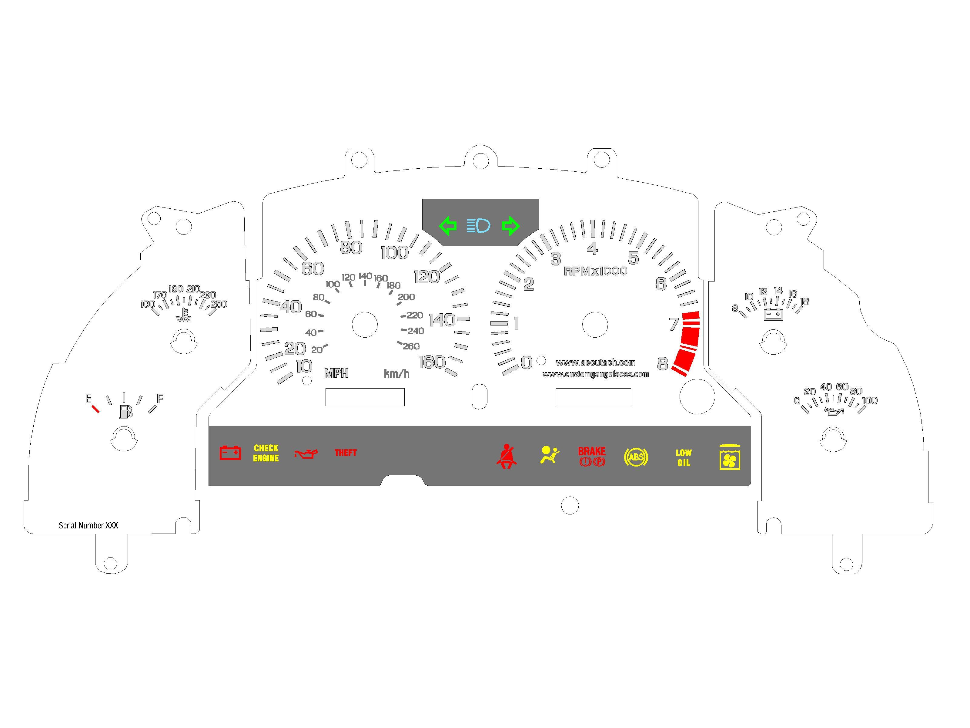
 To get an idea of how these will actually look in the car, but with white marking rather than the stock greenish color (that's coming later) see these Ford Focus faces:
3/2/10:
Scott over at www.customgaugefaces.com has explained to me the limitations of his custom gauge face manufacturing process as it relates to white-faced gauges. He can not make black marks on the faces translucent., so black characters and tick marks must be outlined by translucent white outlines so they can be seen at night or white translucent characters must be outlined in black so they can be seen during the day. Here is an example of the former style on the speedometer and the latter style on the tachometer. I need you all to tell me which you prefer.


I tested the Autometer oil pressure sender with the 94-96 gauge with the 20 ohm resistor shorted out and documented it here.